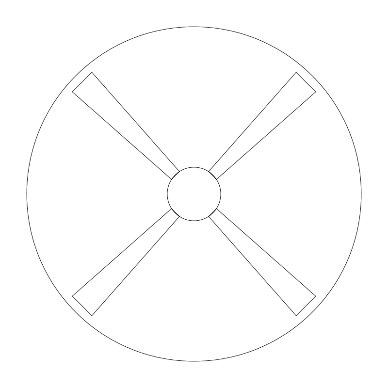
Recessed can light, ceiling-mounted fixture, ceiling fan, a 30in six-arm chandelier, a floor lamp, a 12in floor lamp and a table lamp - seven lighting CAD blocks spanning the reflected ceiling plan and the furniture plan. The 52in fan and the chandelier are the two drawn at a real diameter, because both are objects a table has to be centred under and a person has to clear; the 12in floor lamp is drawn at a real footprint too, every mark inside a 12in square, because it stands on the floor beside the seating. The rest are symbols placed on a grid, and their drawn size means nothing. Every one downloads as a DXF drawn to scale in inches.
7 blocks, 7 downloads on this page. DXF R2018, drawn in inches. Free, no signup.
DWG (R2000, converted from the DXF). PNG is the plan-view preview.
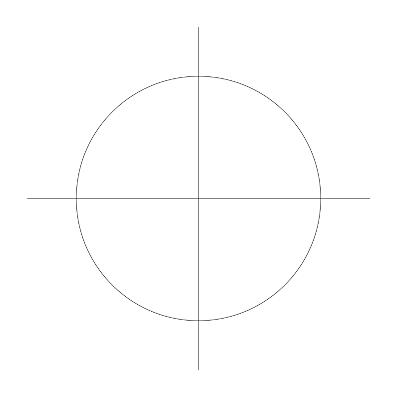
The generic ceiling outlet: a surface or pendant luminaire fed from a ceiling box, not a recessed housing. It carries corridors, closets and utility rooms where no specific product has been picked, with the fixture schedule holding whatever eventually gets bought.
r is symbol radius, not a luminaire dimension. The circle plots at 2r and the four radial ticks run outward to 1.4r, which is where the 11.2in extents come from at the 4in default. Raise r on a 1/16in-scale sheet; drop toward 2in where a dense ceiling grid leaves no room between symbols.
Fixture-center insertion snaps to a room centerline or the middle of a ceiling tile. Keep it on the lighting layer, E-LITE under the AIA layer conventions, rather than power, since the two plot on separate sheets. Leave the four ticks outside the circle: they are the whole difference between this and the recessed symbol at plot scale.
Read against the recessed can on the same reflected ceiling plan. Cans go where a ceiling was designed; this symbol covers the spaces nobody detailed, closets, mechanical rooms and back of house, and the two often share a circuit.
| Plan footprint (W x H) | 11.2in x 11.2in |
|---|---|
| Units | inches |
| DXF version | R2018 |
| Insertion datum | fixture center (ceiling) |
| Parameter | Default | Range / options |
|---|---|---|
| Radius | 4in | 2in–8in |

A downlight housing set into the ceiling plane, appearing in dense arrays on residential kitchen RCPs and commercial lobby layouts. Unlike a surface symbol it implies a ceiling cavity, so plenum depth, joist framing and insulation contact all become questions the moment it lands.
The block is a circle inscribed in a square, and the square is exactly 2r, so extents are 8 x 8in at the 4in default with nothing reading past them. Trim apertures come in a nominal 4, 5 and 6in family while the rough-in housing is larger than any of them, so set r against whichever of the two you need to check clearance for.
Center-point insertion lets ARRAY do the layout: first can off the wall, then step at the photometric spacing. Because the square carries the full extents and no leader strokes fall outside it, the symbol tiles at close spacing without collisions, which is why the square rather than the circle is the outer figure.
Sits below the switch that controls it and, in a kitchen or a lobby, alongside a ceiling-mounted symbol marking the one location that got a decorative fixture instead of a can.
| Plan footprint (W x H) | 8in x 8in |
|---|---|
| Units | inches |
| DXF version | R2018 |
| Insertion datum | fixture center (ceiling) |
| Parameter | Default | Range / options |
|---|---|---|
| Radius | 4in | 2in–8in |
Paddle fan symbol for reflected ceiling plans and residential electrical plans. The circle is drawn at blade sweep, and that sweep is what gets checked against beams, soffits, and the surrounding lighting layout.
The 52in default is the most common residential blade span. The 42-72in range covers a small bedroom or bath fan up to a great-room or covered-patio fan. Span is selected by room area rather than ceiling height, which affects downrod length instead.
The datum is fixture center at the ceiling, so it drops on a room centroid or on quarter points in a multi-fan layout. It belongs on the RCP or electrical layer and should never appear as a solid object on the floor plan.
Drawn with smoke and CO detectors and other ceiling devices on the same reflected ceiling plan, with switch legs shown on the power plan.
| Plan footprint (W x H) | 52in x 52in |
|---|---|
| Units | inches |
| DXF version | R2018 |
| Insertion datum | fixture center (ceiling) |
| Parameter | Default | Range / options |
|---|---|---|
| Diameter | 52in | 42in–72in |
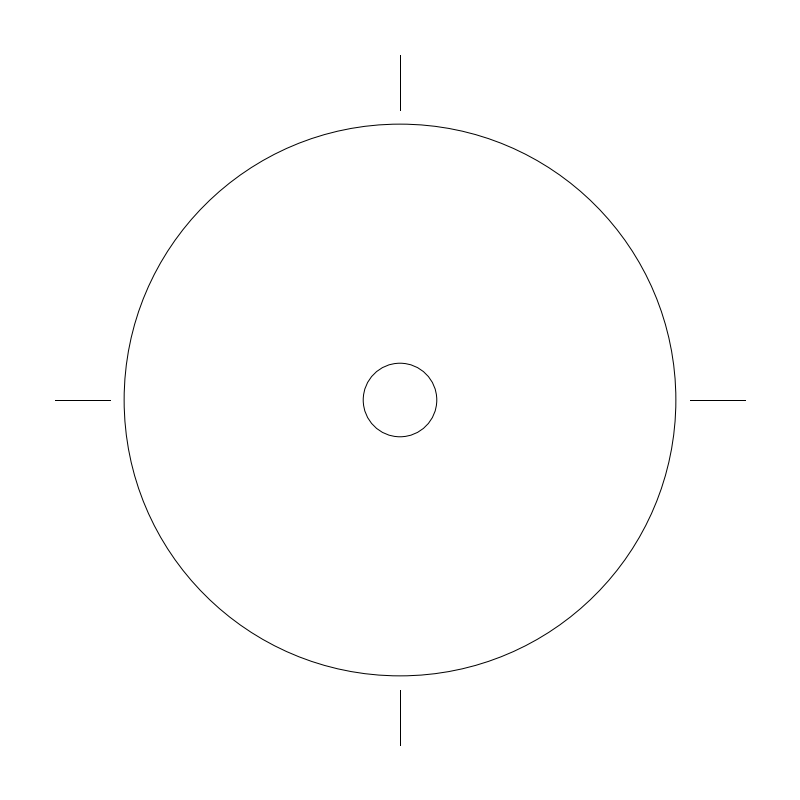
Freestanding floor lamp beside a seating group. On a furniture plan it mostly stakes out the corner it occupies; on a residential electrical plan it justifies a switched receptacle at that specific location.
Default 18in shade diameter, adjustable 14-24in, with a 22.5in bbox that runs 4.5in past the shade. The base is far smaller than the shade, so the circle represents the visual and head-clearance footprint rather than the floor contact area.
Lamp center is the datum, so it drops on a point beside a chair arm or sofa end and needs no rotation. Drawn on the furniture layer but cross-referenced on the electrical plan for the receptacle it requires.
Placed at the shoulder of an accent chair or at the end of the sofa it lights.
| Plan footprint (W x H) | 22.5in x 22.5in |
|---|---|
| Units | inches |
| DXF version | R2018 |
| Insertion datum | lamp center |
| Parameter | Default | Range / options |
|---|---|---|
| Diameter | 18in | 14in–24in |
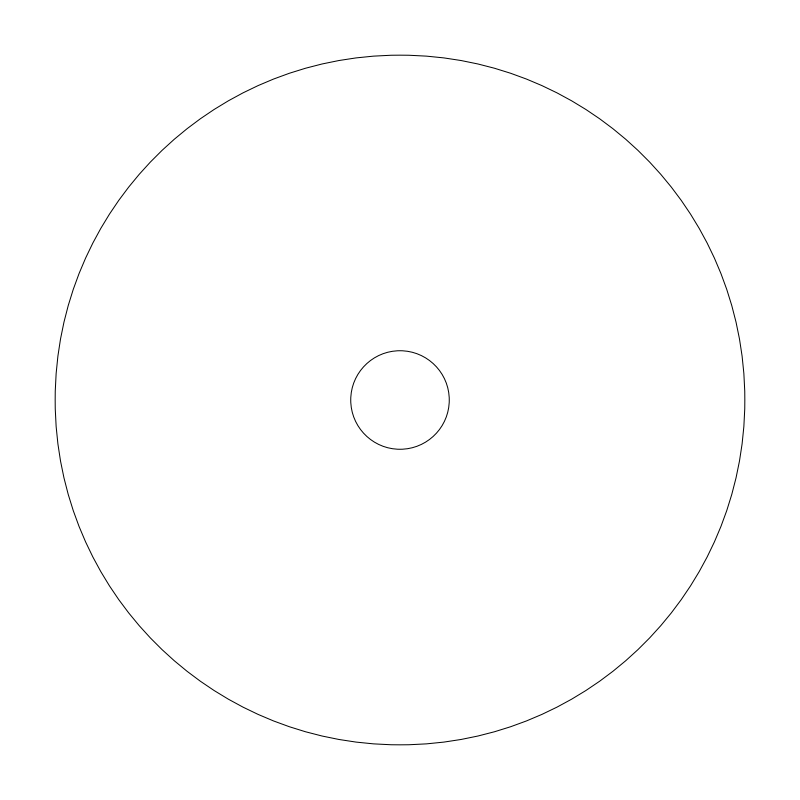
Table lamp shown resting on a nightstand, end table, or console. Because it sits on a surface rather than the floor, it is drawn over the case piece beneath it and belongs last in the stacking order.
Default 14in shade diameter, adjustable 10-18in - deliberately smaller than the floor lamp block. Fourteen inches is a typical bedside shade, 18in a larger console lamp. The bbox matches the diameter exactly, since there is no base flare beyond the shade.
Give it a lighter lineweight than the case piece below so the lamp circle and the furniture edge both stay readable where they overlap at plot scale. Snapping its center datum to the midpoint of the nightstand or console top handles the placement.
Drawn on top of the nightstand beside the bed, or on a TV console or end table in a living room.
| Plan footprint (W x H) | 14in x 14in |
|---|---|
| Units | inches |
| DXF version | R2018 |
| Insertion datum | lamp center |
| Parameter | Default | Range / options |
|---|---|---|
| Diameter | 14in | 10in–18in |
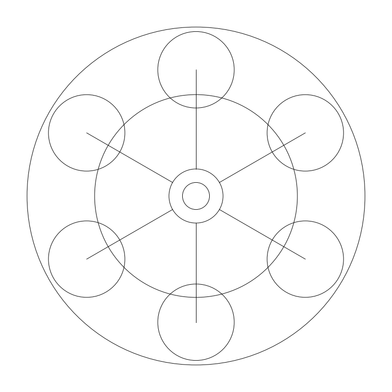
| Plan footprint (W x H) | 30in x 30in |
|---|---|
| Units | inches |
| DXF version | R2018 |
| Insertion datum | fixture center (ceiling); also the outlet box |
| Parameter | Default | Range / options |
|---|---|---|
| Diameter | 30in | 18in–48in |
| Arms | 6in | 3in–12in |
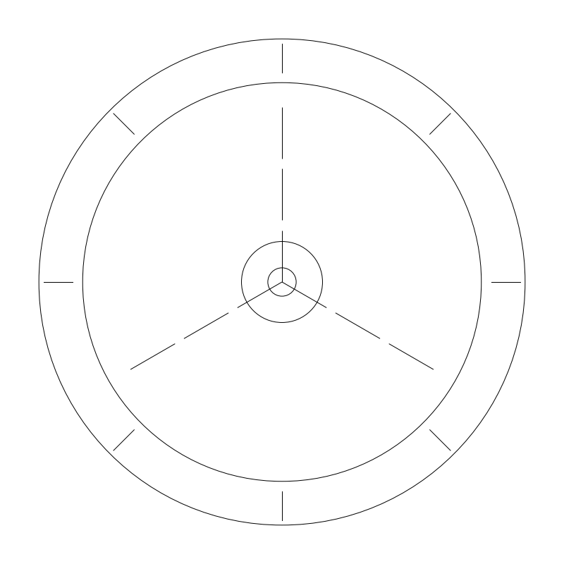
The floor lamp is the task light beside a seat that has no end table, which is how the course lights a chaise, a daybed or a reading chair. Every seating area gets at least one lamp, and no room is lit by a single ceiling fixture alone - an ambient source plus at least one task source is the rule in every living, dining, bedroom and office.
12in shade diameter as drawn, adjustable 10-16in. A floor lamp's footprint on plan is its shade, not its base, because the shade is the widest thing at head height and the base is under the furniture.
Lamp centre is the datum and the block measures exactly 12 x 12in - every mark is inside the shade. That is the difference from the older floor-lamp block, whose glow ticks put an 18in lamp into the catalog at 22.5in and made it collide with furniture it would clear on site.
Set beside a chaise, a daybed or a corner reading chair, and drawn on the electrical or RCP layer alongside the ceiling fixture that provides the room's ambient light.
| Plan footprint (W x H) | 12in x 12in |
|---|---|
| Units | inches |
| DXF version | R2018 |
| Insertion datum | lamp center. Measures exactly 12 x 12 -- every mark is inside the shade, unlike the shipped LAMP-FLOOR whose glow ticks put an 18 in lamp in the catalog at 22.5 in |
| Parameter | Default | Range / options |
|---|---|---|
| Diameter | 12in | 10in–16in |
Standards are listed for drafting context only. A symbol drawn to a convention is not a compliance determination - verify against the governing code and the specified product. See the license and terms.
Fixtures and fans for the reflected ceiling plan. Open one in the editor or take the DXF.
Every category, every MEP orientation, DXF R2018, sorted into folders. Tell us where to send it and the download starts immediately.
If nothing happened, click here to grab the ZIP.