Twenty-two kitchen appliance and equipment CAD blocks: the residential range, two cooktops, a 30in wall oven, 36in refrigerator and 24in dishwasher, an 84x36in island and a 36x16in run of pantry shelving, alongside commercial-kitchen pieces - a 36in commercial range, a 16in fryer, 36in griddle, 54in reach-in refrigerator, two prep tables at 72x30in, a 26in door-type dish machine, a 48in pass shelf, a counter run, a 24x18in countertop microwave, a 72 to 288in bar counter, a 15in bar stool and the walk-in cooler and freezer boxes. Real cabinet and equipment dimensions throughout, since a kitchen plan is a module problem before it is anything else - and the bar counter is drawn as the run rather than as a unit that repeats, because a patron bar is one fabricated piece with two different aisles. Free DXF downloads.
22 blocks, 22 downloads on this page. DXF R2018, drawn in inches. Free, no signup.
DWG (R2000, converted from the DXF). PNG is the plan-view preview.
The 30in freestanding or slide-in range is the residential default, and on plan it drives two things nothing else in the kitchen does: the hood or downdraft directly above it, and the clearance note at flanking combustible cabinets. Gas versus electric changes the utility shown behind the block, not its footprint.
30in wide by 25in deep as drawn. 24in covers apartment and European units built to a 60cm module, and 36in the pro-style width, usually with a deeper body toward the 27in limit and a wider hood above it.
Back-center on the wall line puts the insertion point on the burner centerline, which is the coordinate the hood and the reflected ceiling plan key to. Set the range first and center the hood on that same point rather than on the cabinet opening.
Coordinated with the exhaust hood on the reflected ceiling plan and set opposite the refrigerator and sink; drafters generally keep the dishwasher off the same cabinet run.
| Plan footprint (W x H) | 30in x 25in |
|---|---|
| Units | inches |
| DXF version | R2018 |
| Insertion datum | back-center on wall line |
| Parameter | Default | Range / options |
|---|---|---|
| Width | 30in | 24in–36in |
| Depth | 25in | 24in–27in |
Cooktop and range footprint at the counter run. Kitchen designers use it to set the appliance opening in the cabinet elevation, and MEP drafters use it to locate the gas stub or the 240V range circuit behind it.
Thirty inches is the dominant domestic range width. The 24-36in range covers an apartment range up to a pro-style 36in unit. Depth adjusts 24-27in, matching standard 24in base cabinets with the range body sitting slightly proud of the door face.
Back-center on the wall line, and the record notes this block is an alias of RANGE-30 - drawings referencing either name resolve to the same geometry. Center it to the hood above rather than to the cabinet run, since the two must align.
Drawn with the exhaust hood directly above it and the base cabinet run it interrupts on either side.
| Plan footprint (W x H) | 30in x 25in |
|---|---|
| Units | inches |
| DXF version | R2018 |
| Insertion datum | back-center on wall line (alias of RANGE-30) |
| Parameter | Default | Range / options |
|---|---|---|
| Width | 30in | 24in–36in |
| Depth | 25in | 24in–27in |
A 36in refrigerator sets the tall opening in a residential kitchen plan. What matters on the drawing is less the box than the swing: French doors and freezer drawers sweep into the adjacent counter and aisle, and a hinge set against a return wall will not open far enough to pull the crisper drawers.
36in covers the common French-door and side-by-side widths, 30in a narrow single-door or apartment unit, and 42in a built-in. The 28 to 34in depth runs from a counter-depth body at the low end to a standard-depth one with door and handle included at the high end.
Because the block grows evenly about the insertion point, widening from 36 to 42in leaves that point in place and changes only the flanking cabinet dimensions. Handing is drawn rather than parametric, so mirror the swing arc on its own and leave the block where it sits.
Laid out against the range and dishwasher as the third leg of the work triangle, usually flanked by tall pantry or oven cabinets that fix the opening width.
| Plan footprint (W x H) | 36in x 30in |
|---|---|
| Units | inches |
| DXF version | R2018 |
| Insertion datum | back-center on wall line |
| Parameter | Default | Range / options |
|---|---|---|
| Width | 36in | 30in–42in |
| Depth | 30in | 28in–34in |
The built-in dishwasher drops into the base-cabinet run, nearly always beside the sink so the drain hose and the hot supply share the sink cabinet. On a construction set it earns its place two ways: reserving the cabinet opening for the millwork schedule, and showing the open-door swing against the work aisle.
24in is the standard built-in opening and also the ceiling on this block, since it does not go wider. 18in is the compact machine. The 22 to 25in depth covers the tub plus the door panel and handle standing proud of the cabinet face.
Back-center on the wall line puts the insertion point mid-opening rather than at a corner, so it centers in a 24in gap between cabinets directly. Keep the open-door arc on a clearance layer that plots screened or not at all.
Drawn immediately beside the kitchen sink, and checked against the range and refrigerator when the work triangle and the aisle width are being reviewed.
| Plan footprint (W x H) | 24in x 24in |
|---|---|
| Units | inches |
| DXF version | R2018 |
| Insertion datum | back-center on wall line |
| Parameter | Default | Range / options |
|---|---|---|
| Width | 24in | 18in–24in |
| Depth | 24in | 22in–25in |
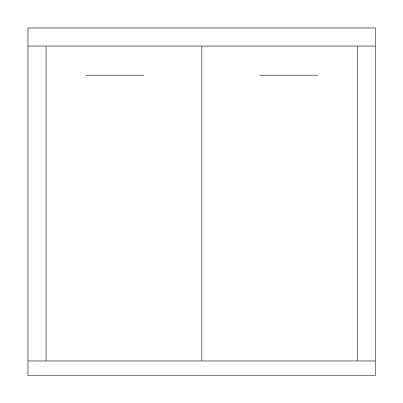
| Plan footprint (W x H) | 24in x 24in |
|---|---|
| Units | inches |
| DXF version | R2018 |
| Insertion datum | back-center on wall line |
| Parameter | Default | Range / options |
|---|---|---|
| Length | 24in | 12in–144in |
| Depth | 24in | 12in–36in |
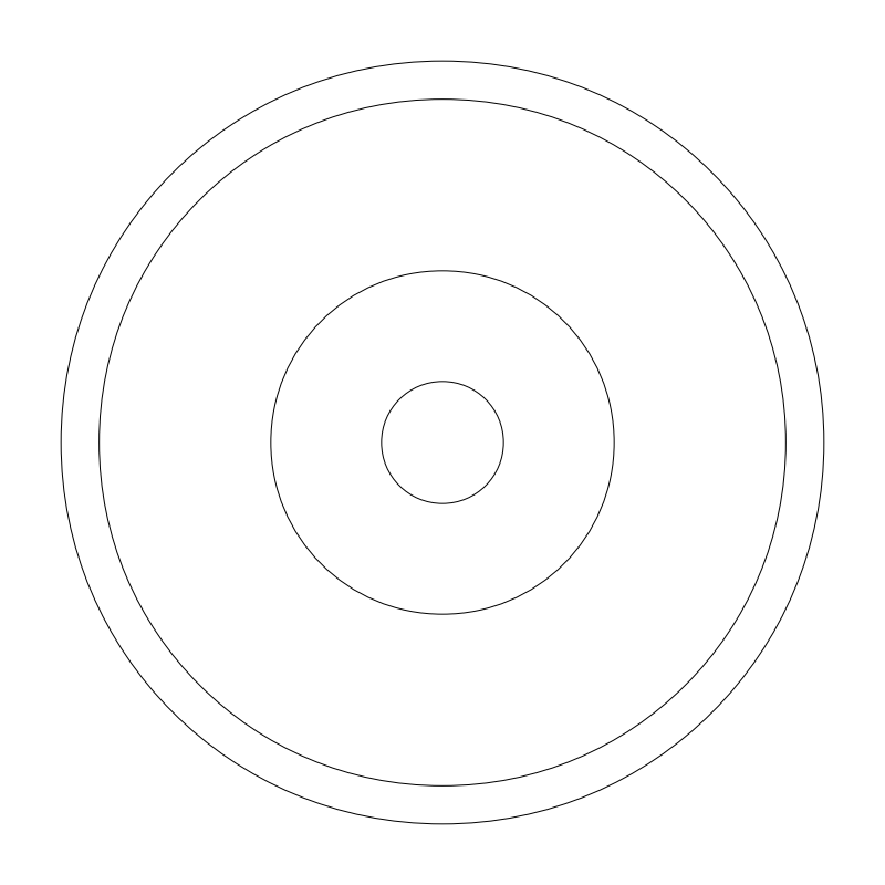
| Plan footprint (W x H) | 15in x 15in |
|---|---|
| Units | inches |
| DXF version | R2018 |
| Insertion datum | seat center |
| Parameter | Default | Range / options |
|---|---|---|
| Diameter | 15in | 13in–18in |
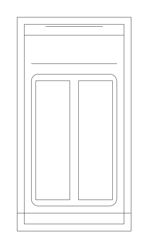
| Plan footprint (W x H) | 16in x 30in |
|---|---|
| Units | inches |
| DXF version | R2018 |
| Insertion datum | back-center on wall line |
| Parameter | Default | Range / options |
|---|---|---|
| Width | 16in | 14in–24in |
| Depth | 30in | 24in–34in |
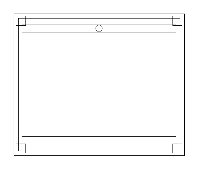
| Plan footprint (W x H) | 36in x 30in |
|---|---|
| Units | inches |
| DXF version | R2018 |
| Insertion datum | back-center on wall line |
| Parameter | Default | Range / options |
|---|---|---|
| Width | 36in | 24in–72in |
| Depth | 30in | 24in–34in |
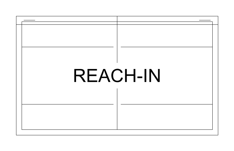
| Plan footprint (W x H) | 54in x 32in |
|---|---|
| Units | inches |
| DXF version | R2018 |
| Insertion datum | back-center on wall line |
| Parameter | Default | Range / options |
|---|---|---|
| Width | 54in | 27in–81in |
| Depth | 32in | 28in–36in |
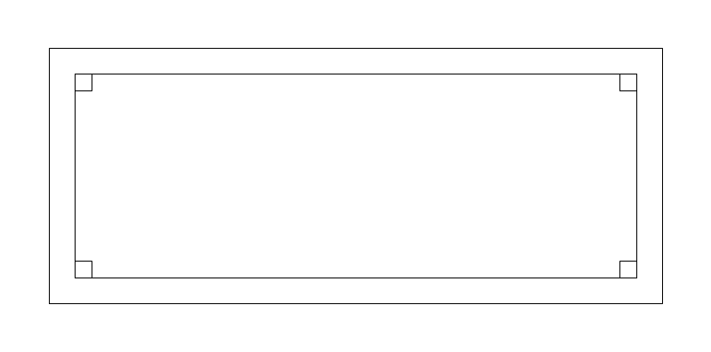
| Plan footprint (W x H) | 72in x 30in |
|---|---|
| Units | inches |
| DXF version | R2018 |
| Insertion datum | back-center on wall line |
| Parameter | Default | Range / options |
|---|---|---|
| Length | 72in | 36in–120in |
| Depth | 30in | 24in–36in |
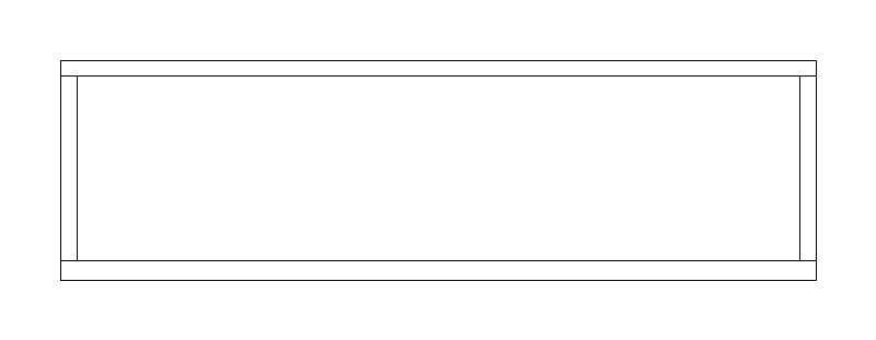
| Plan footprint (W x H) | 48in x 14in |
|---|---|
| Units | inches |
| DXF version | R2018 |
| Insertion datum | back-center on wall line |
| Parameter | Default | Range / options |
|---|---|---|
| Length | 48in | 24in–96in |
| Depth | 14in | 10in–18in |
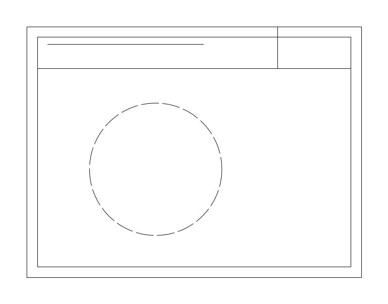
| Plan footprint (W x H) | 24in x 18in |
|---|---|
| Units | inches |
| DXF version | R2018 |
| Insertion datum | back-center on wall line |
| Parameter | Default | Range / options |
|---|---|---|
| Width | 24in | 18in–30in |
| Depth | 18in | 14in–22in |
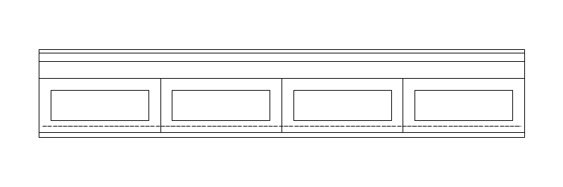
| Plan footprint (W x H) | 144in x 26in |
|---|---|
| Units | inches |
| DXF version | R2018 |
| Insertion datum | back-left corner on wall line (service side at y=0, patrons at +Y) |
| Parameter | Default | Range / options |
|---|---|---|
| Length | 144in | 72in–288in |
| Depth | 26in | 24in–30in |
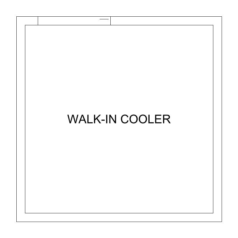
| Plan footprint (W x H) | 96in x 96in |
|---|---|
| Units | inches |
| DXF version | R2018 |
| Insertion datum | back-center on wall line (OUTSIDE face of the panel) |
| Parameter | Default | Range / options |
|---|---|---|
| Width | 96in | 72in–144in |
| Depth | 96in | 72in–144in |
| Label | COOLER | COOLER / FREEZER |
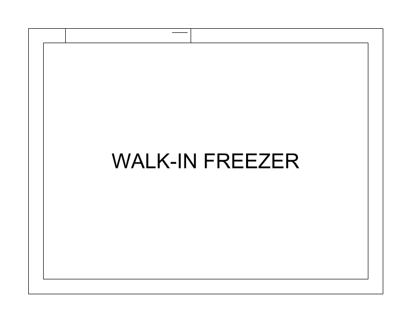
| Plan footprint (W x H) | 96in x 72in |
|---|---|
| Units | inches |
| DXF version | R2018 |
| Insertion datum | back-center on wall line |
| Parameter | Default | Range / options |
|---|---|---|
| Width | 96in | 72in–144in |
| Depth | 72in | 72in–144in |
| Label | FREEZER | COOLER / FREEZER |
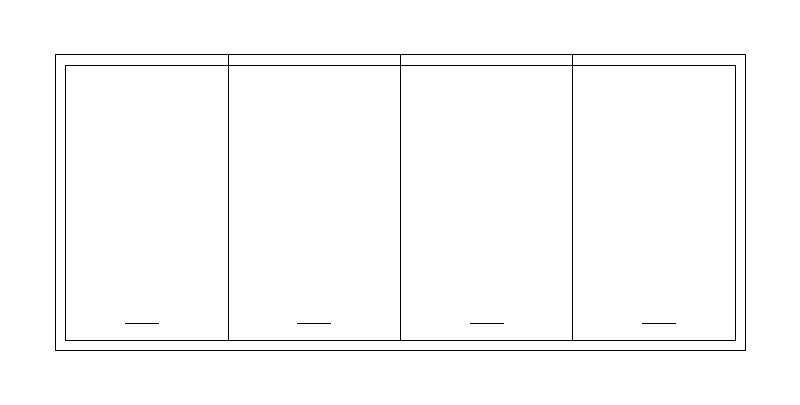
The island is the piece that decides whether a kitchen works, because it is the only fixture with an aisle on all four sides. NKBA puts a work aisle at 42in minimum for one cook and 48in where two cooks work, measured between counter fronts, tall cabinets and appliances - so an 84in island needs the room to be at least 84in plus two aisles wide before anything else is drawn.
84 x 36in as drawn, adjustable 48-144in long and 30-48in deep, with an overhang parameter from 0 to 18in for a seated side. Where the plan claims accessibility, a U-shaped kitchen keeps 60in minimum between opposing arms.
Footprint centre is the datum, because an island stands against nothing and so has no back face to name. The cabinet doors are drawn on the -Y side at a negative offset, which marks the working side; set the overhang parameter rather than stretching the depth when a seated overhang is wanted, so the counter and the knee space stay separable.
Checked against the work triangle, where no leg may intersect an island by more than 12in, and against the traffic pattern, since no major path crosses the triangle.
| Plan footprint (W x H) | 84in x 36in |
|---|---|
| Units | inches |
| DXF version | R2018 |
| Insertion datum | footprint center (an island stands against nothing, so there is no back face to name) |
| Parameter | Default | Range / options |
|---|---|---|
| Length | 84in | 48in–144in |
| Depth | 36in | 30in–48in |
| Overhang | 0in | 0in–18in |
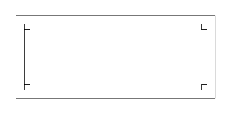
The stainless prep table is the commercial kitchen's work surface, placed where the flow needs a landing between two pieces of equipment. Unlike a residential counter run it stands free of the wall as often as against it, and it is the piece a plan moves first when an aisle comes up short.
72 x 30in as drawn, adjustable 36-120in long and 24-36in deep. 30in is the commercial depth; the 24in end of the range is a residential counter depth and the 36in end is a two-sided table worked from both faces.
Back-centre on the wall line is the datum and the open work face is marked at the front, so the block cannot be set in backwards against a wall. Where the table stands free in the room, the marked face is the primary working side and the aisle behind it still has to be drawn.
Set in the line between the cooking equipment and the dish area, with the work aisle held at 42in for one cook and 48in for two.
| Plan footprint (W x H) | 72in x 30in |
|---|---|
| Units | inches |
| DXF version | R2018 |
| Insertion datum | back-center on wall line |
| Parameter | Default | Range / options |
|---|---|---|
| Length | 72in | 36in–120in |
| Depth | 30in | 24in–36in |
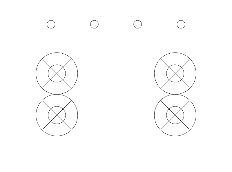
The drop-in cooktop, which differs from a range on plan in one way that matters: the oven is somewhere else, usually a wall oven, so the cooking surface and the oven are two separate fixtures with two separate landings. The cooktop is one leg of the work triangle; the wall oven is not.
30 x 21in as drawn, adjustable 24-36in wide and 19-24in deep. 30in is the residential default; 36in is the pro width. The 21in depth is the cutout rather than the cabinet, which is why it is shallower than the 25in a range takes.
Back-centre on the wall line is the datum and the control knobs mark the front. Where the cooktop sits in an island or a peninsula, the counter has to extend at least 9in behind it, which is a dimension the block does not carry and the plan must.
Drawn with the wall oven it replaces the range with, and with the hood above it on the reflected ceiling plan keyed to the same centreline.
| Plan footprint (W x H) | 30in x 21in |
|---|---|
| Units | inches |
| DXF version | R2018 |
| Insertion datum | back-center on wall line |
| Parameter | Default | Range / options |
|---|---|---|
| Width | 30in | 24in–36in |
| Depth | 21in | 19in–24in |
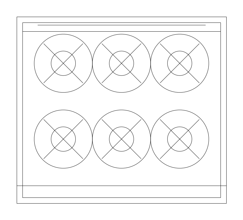
The commercial range, and the anchor of a restaurant cook line. It sits under the hood and everything else on the line is placed relative to it, so it goes down first and the landings, the fryer and the griddle follow.
36 x 32in as drawn, adjustable 24-60in wide and 30-36in deep. The 32in depth is the commercial body, 7in deeper than a residential 30in range, which is what makes a commercial line need a deeper wall run than a domestic kitchen.
Back-centre on the wall line is the datum with the oven door and handle marking the front, so the block sets against the cook-line wall and the hood centres on the same point. The published depth is the body; the open oven door is not in the block and has to be checked against the aisle behind it.
Drawn in the cook line with the fryer and the griddle, under a hood on the reflected ceiling plan, with the work aisle behind it at 48in where two cooks work.
| Plan footprint (W x H) | 36in x 32in |
|---|---|
| Units | inches |
| DXF version | R2018 |
| Insertion datum | back-center on wall line |
| Parameter | Default | Range / options |
|---|---|---|
| Width | 36in | 24in–60in |
| Depth | 32in | 30in–36in |
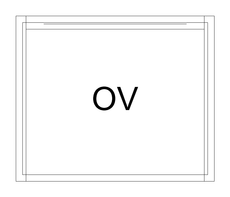
The wall oven is the oven half of a cooktop kitchen, built into a tall cabinet rather than standing on the floor. NKBA treats a full-height, full-depth obstacle - a tall oven cabinet among them - as something that never stands between two primary work centres, which is the placement rule that governs this block rather than any landing dimension.
30 x 25in as drawn, adjustable 24-36in wide and 24-27in deep. The 25in depth is the cabinet the oven is built into, not the appliance, which is why it matches a base-cabinet run rather than the 21in of a cooktop cutout.
Back-centre on the wall line, oven door and handle marking the front. Because the block is the cabinet footprint, a stack of two ovens occupies the same plan footprint as one - the difference is in elevation, and the plan should note it rather than show it.
Drawn with COOKTOP-30, since a wall oven and a cooktop together replace a single range.
| Plan footprint (W x H) | 30in x 25in |
|---|---|
| Units | inches |
| DXF version | R2018 |
| Insertion datum | back-center on wall line |
| Parameter | Default | Range / options |
|---|---|---|
| Width | 30in | 24in–36in |
| Depth | 25in | 24in–27in |
The door-type commercial dish machine, and the fixture the dish area is built around. It needs a soiled landing on one side and a clean landing on the other, so on plan it is never drawn alone - the two tables beside it are what make it work, and they take more room than the machine does.
26 x 28in as drawn, adjustable 24-30in wide and 26-32in deep. A door-type machine is small in plan and tall in elevation: the hood lifts, which is why the depth is the body and the clearance above it does not show here.
Back-centre on the wall line is the datum and the hood lift handle marks the front. Draw the soiled and clean landings as separate surfaces either side rather than stretching this block, since the flow direction through them is what a health inspector reads.
Set between a soiled dish table and a clean landing, with the three-compartment sink in the same room.
| Plan footprint (W x H) | 26in x 28in |
|---|---|
| Units | inches |
| DXF version | R2018 |
| Insertion datum | back-center on wall line |
| Parameter | Default | Range / options |
|---|---|---|
| Width | 26in | 24in–30in |
| Depth | 28in | 26in–32in |
Open pantry shelving, drawn as a shelf run against a wall. In a residential kitchen the pantry is the tall obstacle NKBA keeps out from between two work centres; in a commercial one it is dry storage and sits off the cook line entirely.
36 x 16in as drawn with 4 shelves, adjustable 18-96in long, 12-24in deep and 2-8 shelves. 16in is the depth a can or a box sits on without a second row going lost behind it.
Back-centre on the wall line is the datum and the open shelf face marks the front. The shelf count is a parameter rather than geometry in plan - all four shelves draw as one rectangle - so the count belongs in the schedule where it will be read.
Drawn on the wall opposite the work triangle rather than inside it, so a person fetching from it does not cross the cook's path.
| Plan footprint (W x H) | 36in x 16in |
|---|---|
| Units | inches |
| DXF version | R2018 |
| Insertion datum | back-center on wall line |
| Parameter | Default | Range / options |
|---|---|---|
| Length | 36in | 18in–96in |
| Depth | 16in | 12in–24in |
| Shelves | 4in | 2in–8in |
Standards are listed for drafting context only. A symbol drawn to a convention is not a compliance determination - verify against the governing code and the specified product. See the license and terms.
Appliances at real cabinet dimensions for the residential plan. Open one in the editor or take the DXF.
Every category, every MEP orientation, DXF R2018, sorted into folders. Tell us where to send it and the download starts immediately.
If nothing happened, click here to grab the ZIP.